Folks,
I know it has been awhile since my last update. Some forward motion was made on the EKGen.
I won't bore you how I ran to the hobby store to pick up brass strips and brass tubing for the high voltage capacitors.
I also won't bore you how I had to take the photos, download them to my computer, pick the right ones to use and upload them to my server. Plus, the forum and some of the members have been keeping me busy!

From a handful of parts like this,
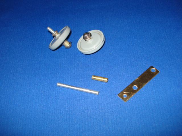
The parts shown above were for one stage of the EKGen. I assembled the high voltage (HV) doorknob capacitors according to Fig. 4a of patent # 3022430. The HV capacitor rail now looks like this:
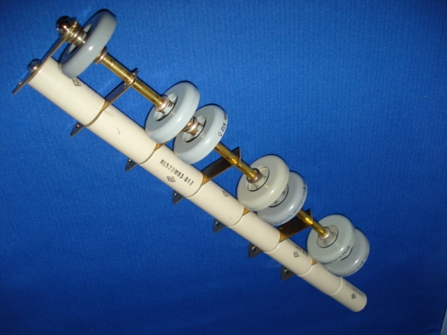
Seven stages are shown. The tabs on the left side will be used to attach the disk elements (tin can lids) of the EKGen. I plan on using small stainless 4-40 machine screws i had available. That way I may be able to swap out disk elements to make modifications in the hole sizing, flaring, etc. The tabs are also a better way to secure the disk elements rather than pinch them together by using the insulators as in this earlier photo.
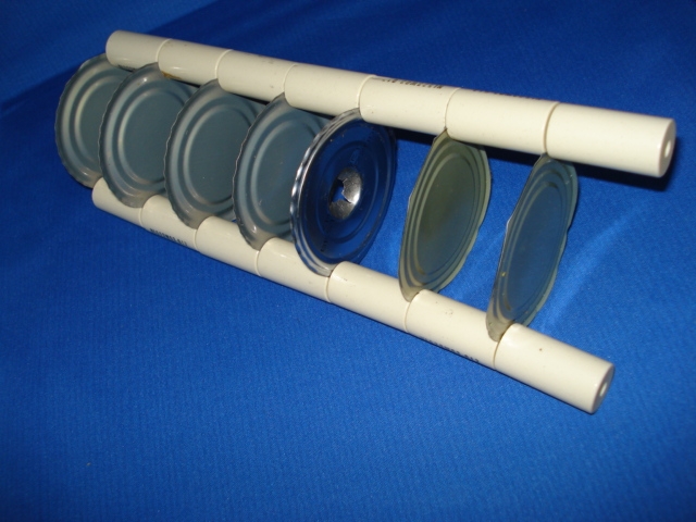
In this early photo showing the stacking of the disk elements (tin can lids), you can see one hole flared out with a ball pein hammer. This is prior to purchasing the doming kit. Before I flare the holes for the disk elements as indicated on Fig. 4b or 4c of US pat # 3022430, I may wish to mount the HV capacitor rail and the disk element support rail (the other group of insulators).
I will assemble the supports and add the propane nozzle near the bottom of the disk stack. The flame will go up through the center of the lids through the holes which I have to make in the disk elements (lids). The blowtorch nozzle must be supported and that is what I will work on next.
As Mikado noted, when I drill and flare the holes for the disk elements, I must be careful of Coanda forces. This is where fluid flow will flow along curved surfaces like this:

Dr. Brown eliminated Coanda forces by placing the edge of the flare of one disk element almost into the throat of the next disk element as shown in Fig. 4a of his patent. My ceramic standoffs are 1.5 inches long and I do not know if I can flare it as deep as Dr. Brown depicted. I am limited by the length of the ceramic standoff. It would have been nicer to have a shorter standoff but that is what was cheap and available at the time. Hopefully it will not make much of a difference and that is why I made the disk elements removable. I may also use a screen for the last element as depicted on Fig. 3 of his patent. This would be later on down the line after I build the proof of concept (POC) model.
Well, back to work. I have more to do on the EKGen. With the weekend coming up, I hope I can make some more forward progress on the device. I will take more pictures and show more progress at a later time.
May the FORCE be with you and have a magical day!
MagicBill